[PYTHON] I tried using the Pi Console I / F of the Raspberry Pi IoT starter kit "anyPi" from Mechatrax.
Introduction
In this article, I will use the equipment I have except for the PiConsole I / F, but the PiConsole I / F is a bundled item exclusively for Mechatrax's Raspberry Pi IoT starter kit "[anyPi] [anyPi URL]". That's right, it seems that it is not sold separately. I would appreciate your attention.
"[AnyPi] [anyPi URL]" is a starter kit for IoT that allows you to connect Raspberry Pi to the Internet in 3 minutes even if you do not have an Internet connection environment, and there is really a setup introduction video of 3 minutes or less. I will introduce you.
[ ](http: / /www.youtube.com/watch?v=NhrIYOyh4wc)
(The link is a video.)
](http: / /www.youtube.com/watch?v=NhrIYOyh4wc)
(The link is a video.)
The following articles are based on the assumption that they have been assembled according to the [anyPi] and [anyPi URL] sites.
Equipment used
The following equipment is used in this article. No soldering or processing is required.
- PiConsole I/F --Raspberry Pi 3
- 3GPI --USB mini B cable (for serial) --AC adapter (↑↑↑ Up to this point, what is included in [anyPi] [anyPi URL]) (↓ ↓ ↓ The following are not included in [anyPi] [anyPi URL]: There is no problem if some samples cannot be executed except for PC)
--PC (Windows machine) --I2C connection temperature sensor (http://akizukidenshi.com/catalog/g/gM-06675/)
- PiCamera
- bread board --Jumper cable appropriate amount
Since it has a header connector that can be directly connected to the Raspberry Pi, it has a three-story structure with a similar 3GPI with a header connector. I remembered PC / 104 and GP-IB (HP-IB).

The script created as a sample is uploaded to the following github.
https://github.com/syasuder/piconsole-sample
If copying sutras is troublesome, please use clone etc.
Log in to Raspberry Pi with a serial connection from a personal computer (Win system)
(If you connect with a wired / wireless LAN and use a terminal emulator via ssh, skip this section and proceed to the basics.)
The PiConsole I / F has a USB / serial (UART) conversion circuit. You can access the Raspberry Pi serial just by connecting it to your PC with a USB mini B cable.
In addition, the serial is set to tty by default, so you don't have to do anything just by connecting it.
You can tell that you don't have to do anything by launching a terminal emulator (TeraTerm is used here) and then turning on the Raspberry Pi. 115,200bps, 8 bits of data, 1 stop bit, no parity.
-Serial output during rasp pie boot

However, when you connect to the PiConsole I / F via USB for the first time, it will take some time for the driver to be installed, so you may not be able to see this boot log. If it was Windows 8.1 at hand, it was recognized by the driver attached to the OS, but it still took tens of seconds.
・ COM port recognized

So the screen of the terminal emulator you see for the first time may look like the one below.
・ It's pitch black when you connect for the first time

In this case, hit the Enter key. You should see a login prompt.
・ Login is possible

Try logging in as the default user for Raspberry Pi.
Username: pi Password: raspberry
On a terminal emulator
Raspbian GNU/Linux 8 raspberrypi ttyAMA0

raspberrypi login: pi
Password:
Last login: Mon Feb  8 16:03:40 JST 2016 on ttyAMA0
Linux raspberrypi 4.1.17-v7+ #834 SMP Mon Feb 1 15:17:54 GMT 2016 armv7l

The programs included with the Debian GNU/Linux system are free software;
the exact distribution terms for each program are described in the
individual files in /usr/share/doc/*/copyright.

Debian GNU/Linux comes with ABSOLUTELY NO WARRANTY, to the extent
permitted by applicable law.
If you are accustomed to connecting with ssh via LAN, you may be confused by the serial connection terminal. Here, only the following two measures are taken. (Reference: [Qiita: Serial communication with RaspberryPi3] URL for serial communication with RaspberryPi3)
--Terminal size --Supports 256 colors
First, check the problem.
・ The terminal size is disappointing

On a terminal emulator
pi@raspberrypi:~$ stty rows 36; stty columns 128
pi@raspberrypi:~$ export TERM=xterm-256color; source ~/.bashrc
・ Spacious & 256 colors

Change the number of lines and digits according to your environment.
After that, you can use it like a terminal connected with ssh, but it is better to update or add packages, etc. via wired / wireless LAN. If you are using a DHCP-enabled LAN environment, just plug in the wired LAN cable.
I think one of the advantages of connecting serially is that the terminal emulator can be left open even when the Raspberry Pi is turned on and off. Depending on the functionality of your terminal emulator, do you find reconnecting via ssh a hassle?
Basic edition
From here, we will check the operation of each function installed in the PiConsole I / F individually.
GPIO
First, check the operation of the buttons, LEDs, and buzzer.
Use the gpio command. The gpio command can be used without installing it, but it seems that the 3GPI image 3gpi-20160208-2gb.img does not support Raspberry Pi 3 as shown below.
On a terminal emulator
pi@raspberrypi:~ $ gpio readall
Oops - unable to determine board type... model: 8
・ ・ ・
pi@raspberrypi:~ $ gpio -v
gpio version: 2.31
Copyright (c) 2012-2015 Gordon Henderson
This is free software with ABSOLUTELY NO WARRANTY.
For details type: gpio -warranty

Raspberry Pi Details:
  Type: Unknown08, Revision: 02, Memory: 1024MB, Maker: Sony
  Device tree is enabled.
  This Raspberry Pi supports user-level GPIO access.
    -> See the man-page for more details
It says "Type: Unknown 08". Therefore, update the wiringpi package.
On a terminal emulator
pi@raspberrypi:~ $ sudo apt-get install wiringpi
・ ・ ・
pi@raspberrypi:~ $ gpio -v
gpio version: 2.32
Copyright (c) 2012-2015 Gordon Henderson
This is free software with ABSOLUTELY NO WARRANTY.
For details type: gpio -warranty

Raspberry Pi Details:
  Type: Pi 3, Revision: 02, Memory: 1024MB, Maker: Sony
  * Device tree is enabled.
  * This Raspberry Pi supports user-level GPIO access.
    -> See the man-page for more details
    -> ie. export WIRINGPI_GPIOMEM=1
Recognized as "Type: Pi 3". There are various settings for Raspberry Pi gpio, so first check the original settings.
On a terminal emulator
pi@raspberrypi:~ $ gpio readall
 +-----+-----+---------+------+---+---Pi 3---+---+------+---------+-----+-----+
 | BCM | wPi |   Name  | Mode | V | Physical | V | Mode | Name    | wPi | BCM |
 +-----+-----+---------+------+---+----++----+---+------+---------+-----+-----+
 |     |     |    3.3v |      |   |  1 || 2  |   |      | 5v      |     |     |
 |   2 |   8 |   SDA.1 | ALT0 | 1 |  3 || 4  |   |      | 5V      |     |     |
 |   3 |   9 |   SCL.1 | ALT0 | 1 |  5 || 6  |   |      | 0v      |     |     |
 |   4 |   7 | GPIO. 7 |   IN | 1 |  7 || 8  | 1 | ALT0 | TxD     | 15  | 14  |
 |     |     |      0v |      |   |  9 || 10 | 1 | ALT0 | RxD     | 16  | 15  |
 |  17 |   0 | GPIO. 0 |  OUT | 0 | 11 || 12 | 0 | IN   | GPIO. 1 | 1   | 18  |
 |  27 |   2 | GPIO. 2 |  OUT | 0 | 13 || 14 |   |      | 0v      |     |     |
 |  22 |   3 | GPIO. 3 |   IN | 1 | 15 || 16 | 0 | IN   | GPIO. 4 | 4   | 23  |
 |     |     |    3.3v |      |   | 17 || 18 | 0 | IN   | GPIO. 5 | 5   | 24  |
 |  10 |  12 |    MOSI |   IN | 0 | 19 || 20 |   |      | 0v      |     |     |
 |   9 |  13 |    MISO |   IN | 0 | 21 || 22 | 0 | IN   | GPIO. 6 | 6   | 25  |
 |  11 |  14 |    SCLK |   IN | 0 | 23 || 24 | 1 | IN   | CE0     | 10  | 8   |
 |     |     |      0v |      |   | 25 || 26 | 1 | IN   | CE1     | 11  | 7   |
 |   0 |  30 |   SDA.0 |   IN | 1 | 27 || 28 | 1 | IN   | SCL.0   | 31  | 1   |
 |   5 |  21 | GPIO.21 |   IN | 1 | 29 || 30 |   |      | 0v      |     |     |
 |   6 |  22 | GPIO.22 |   IN | 1 | 31 || 32 | 0 | IN   | GPIO.26 | 26  | 12  |
 |  13 |  23 | GPIO.23 |   IN | 0 | 33 || 34 |   |      | 0v      |     |     |
 |  19 |  24 | GPIO.24 |   IN | 1 | 35 || 36 | 1 | IN   | GPIO.27 | 27  | 16  |
 |  26 |  25 | GPIO.25 |   IN | 0 | 37 || 38 | 0 | IN   | GPIO.28 | 28  | 20  |
 |     |     |      0v |      |   | 39 || 40 | 0 | IN   | GPIO.29 | 29  | 21  |
 +-----+-----+---------+------+---+----++----+---+------+---------+-----+-----+
 | BCM | wPi |   Name  | Mode | V | Physical | V | Mode | Name    | wPi | BCM |
 +-----+-----+---------+------+---+---Pi 3---+---+------+---------+-----+-----+
Let me explain a little about the above table. The Physical column corresponds to the pin number of the Raspberry Pi header pin. In this article, the gpio number uses the so-called "GPIO number", so in the above table it corresponds to the number written in the "BCM" column. The GPIO number is also used in the script. For example, GPIO20 is on pin 38 of the header pin.
Now that you know how to check the GPIO number mapping, let's start with L-Pika. Turn on the LED.
On a terminal emulator
pi@raspberrypi:~ $ gpio -g mode 20 out
pi@raspberrypi:~ $ gpio -g mode 21 out
pi@raspberrypi:~ $ gpio -g write 20 1
(Red LED lights up)
pi@raspberrypi:~ $ gpio -g write 21 1
(Red / yellow LED lights)
pi@raspberrypi:~ $ gpio -g write 20 0
pi@raspberrypi:~ $ gpio -g write 21 0
・ Red / yellow LED lighting status

Check the IO of the PiConsole I / F before the rest of the check.
Table 1: GPIO for use with PiConsole I / F
| GPIO name | PIN number | Setting | function |
|---|---|---|---|
| GPIO20 | 38 | output | LED1(Red) |
| GPIO21 | 40 | output | LED2(yellow) |
| GPIO25 | 22 | output | buzzer |
| GPIO19 | 35 | input | SW1(White) |
| GPIO16 | 36 | input | SW2(black) |
The following does not operate the pins directly.
Table 2: GPIO for use with PiConsole I / F
| GPIO name | PIN number | function |
|---|---|---|
| GPIO2 | 3 | Liquid crystal SDA |
| GPIO3 | 5 | Liquid crystal SCL |
| GPIO14 | 8 | USB232 conversion(TXD) |
| GPIO15 | 10 | USB232 conversion(RXD) |
Let's continue. It is a buzzer. It makes a fairly loud noise.
On a terminal emulator
pi@raspberrypi:~ $ gpio -g mode 25 out
pi@raspberrypi:~ $ gpio -g write 25 1
pi@raspberrypi:~ $ gpio -g write 25 0
Next is SW. SW becomes '0' when pressed. (So-called negative logic)
On a terminal emulator
pi@raspberrypi:~ $ gpio -g read 19
1
pi@raspberrypi:~ $ gpio -g read 19
0
(SW1 white button pressed state)
pi@raspberrypi:~ $ gpio -g read 16
1
pi@raspberrypi:~ $ gpio -g read 16
0
(SW2 black button pressed state)
That's all for GPIO confirmation.
I2C
The LCD module is connected to the Raspberry Pi via the I2C bus. To use the I2C bus, I2C must be enabled in raspi-config.
raspi-config>Advanced Options>I2C
Install the tool for checking the operation.
On a terminal emulator
pi@raspberrypi:~ $ sudo apt-get install i2c-tools
Since I2C is a bus, you can connect multiple devices in a string. That means you need to identify the device. Check the recognition status of the device with the tool installed immediately.
On a terminal emulator
pi@raspberrypi:~ $ sudo i2cdetect -y 1
     0  1  2  3  4  5  6  7  8  9  a  b  c  d  e  f
00:          -- -- -- -- -- -- -- -- -- -- -- -- --
10: -- -- -- -- -- -- -- -- -- -- -- -- -- -- -- --
20: -- -- -- -- -- -- -- -- -- -- -- -- -- -- -- --
30: -- -- -- -- -- -- -- -- -- -- -- -- -- -- 3e --
40: -- -- -- -- -- -- -- -- -- -- -- -- -- -- -- --
50: -- -- -- -- -- -- -- -- -- -- -- -- -- -- -- --
60: -- -- -- -- -- -- -- -- -- -- -- -- -- -- -- --
70: -- -- -- -- -- -- -- --
This '3e' is the address of the LCD module. To check the operation of the LCD module, use the script "[Qiita: AQM0802A / ST7032i LCD display using WiringPi-Python] URL of AQM0802A / ST7032i LCD display using WiringPi-Python". I need the python module of wiringpi, so install it with pip3.
On a terminal emulator
pi@raspberrypi:~/sandbox $ sudo pip3 install wiringpi
Change the following line in the script of the above Qiita article.
import wiringpi2 as wp
Where it is
import wiringpi as wp
Change to.
When executed, the ticker will be displayed on the LCD screen.
On a terminal emulator
pi@raspberrypi:~/sandbox $ python3 st7032i.py

This completes the I2C operation check.
Sample 1: LED lights when button is pressed
Let's write a simple python script using wiringpi. First is the cooperation between buttons and LEDs.
・ Sample that LED lights up when the button is pressed
b1.py
#!/usr/bin/env python3
# -*- coding:utf-8 -*-

import wiringpi as wp
PIN_SW1_WHITE = 19
PIN_SW2_BLACK = 16
PIN_LED1_RED = 20
PIN_LED2_YELLOW = 21
PIN_BUZZER = 25

if __name__ == '__main__':
    wp.wiringPiSetupGpio()
    wp.pinMode(20,1)
    wp.pinMode(21,1)
    wp.pinMode(25,1)
    while True:
        sw1 = wp.digitalRead(PIN_SW1_WHITE)
        sw2 = wp.digitalRead(PIN_SW2_BLACK)

        #Since sw is negative logic, it is inverted and set to LED output.
        wp.digitalWrite(PIN_LED1_RED, ~sw1 & 1)
        wp.digitalWrite(PIN_LED2_YELLOW, ~sw2 & 1)
        wp.delay(250)
Execute as follows.
On a terminal emulator
pi@raspberrypi:~/sandbox $ sudo python3 b1.py
Press SW1 (white) to turn on LED1 (red), and press SW2 (black) to turn on LED2 (yellow).
Sample 2: Press and hold button to reboot / shut down
You can work with anything you can do with python scripts. In this sample, the detection of SW press is described in interrupt style with wiringPiISR.
b2.py
#!/usr/bin/env python3
# -*- coding:utf-8 -*-

import wiringpi as wp
PIN_SW1_WHITE = 19
PIN_SW2_BLACK = 16
PIN_LED1_RED = 20
PIN_LED2_YELLOW = 21
PIN_BUZZER = 25

import os

#Press and hold for 1 second or longer to return True
def is_long_pushed(pin):
    count = 0;
    while count < 4:
        state = wp.digitalRead(pin)
        if state != 0:
            return False
        count = count + 1
        wp.delay(250)
    return True

#Callback with sw1 pressed
def sw1_callback():
    if is_long_pushed(PIN_SW1_WHITE):
        print("reboot")
        os.system("sudo reboot")
    else:
        print("reboot cancel")

#Callback with sw2 pressed
def sw2_callback():
    if is_long_pushed(PIN_SW2_BLACK):
        print("shutdown")
        os.system("sudo poweroff")
    else:
        print("shutdown cancel")

if __name__ == '__main__':
    wp.wiringPiSetupGpio()
    wp.pinMode(20,1)
    wp.pinMode(21,1)
    wp.pinMode(25,1)
    #Fall trigger because it is negative logic
    wp.wiringPiISR(PIN_SW1_WHITE, wp.GPIO.INT_EDGE_FALLING, sw1_callback)
    wp.wiringPiISR(PIN_SW2_BLACK, wp.GPIO.INT_EDGE_FALLING, sw2_callback)
    while True:
        wp.delay(250)
I will do it.
On a terminal emulator
pi@raspberrypi:~/sandbox $ sudo python3 b1.py
(SW1(White)Long press)
reboot
[ 3388.810715] reboot: Restarting system
・ ・ ・
On a terminal emulator
pi@raspberrypi:~/sandbox $ sudo python3 b1.py
(SW2(black)Long press)
shutdown
[  123.228773] reboot: Power down
・ ・ ・
Sample 3: Press the button to display the current IP address on the LCD
It is simple because the class used to check the operation of the LCD module is imported and used. Save it as st7032i.py.
b3.py
#!/usr/bin/env python3
# -*- coding:utf-8 -*-

import wiringpi as wp
PIN_SW1_WHITE = 19
PIN_SW2_BLACK = 16
PIN_LED1_RED = 20
PIN_LED2_YELLOW = 21
PIN_BUZZER = 25

import sys, socket, struct
from fcntl import ioctl
SIOCGIFADDR = 0x8915

from st7032i import St7032iLCD as LCD
I2C_ADDR_LCD = 0x3e

def get_ip(interface):
    s = socket.socket(socket.AF_INET, socket.SOCK_DGRAM)
    try:
        ifreq  = struct.pack(b'16s16x', interface)
        ifaddr = ioctl(s.fileno(), SIOCGIFADDR, ifreq)
    finally:
        s.close()
    _, sa_family, port, in_addr = struct.unpack(b'16sHH4s8x', ifaddr)
    return (socket.inet_ntoa(in_addr))

if __name__ == '__main__':
    wp.wiringPiSetupGpio()
    wp.pinMode(20,1)
    wp.pinMode(21,1)
    wp.pinMode(25,1)
    while True:
        sw1 = wp.digitalRead(PIN_SW1_WHITE)
        sw2 = wp.digitalRead(PIN_SW2_BLACK)
        if sw1 == 0:
            ip_addr_eth0 = get_ip(b'eth0')
            lcd = LCD(I2C_ADDR_LCD)
            lcd.clear()
            wp.delay(500)
            lcd.set_cursor(0, 0)
            lcd.print(ip_addr_eth0)
        wp.delay(250)
I will try it.
On a terminal emulator
pi@raspberrypi:~/sandbox $ sudo python3 b3.py
If you press the black switch, the address of the eth0 interface will be displayed on the LCD.
・ IP address display

If you change the'eth0'part on the script to'ppp0', the 3G ppp address will be displayed.
Sample 4: Press the button to display the current temperature on the LCD
(If you do not have an I2C-connected temperature sensor module, skip this item.)
Wire while referring to the material of the temperature sensor module of I2C connection (http://akizukidenshi.com/catalog/g/gM-06675/). It's easy because there are only four.
・ Pin correspondence table (PIN number on the module side is temporary)
| Temperature sensor module side | (PIN number) | PIN number | Raspberry Pi side |
|---|---|---|---|
| VDD | (1) | 1 | 3.3v |
| SDA | (3) | 3 | SDA |
| SCL | (2) | 5 | SCL |
| GND | (4) | 6 | GND |
・ Temperature sensor module wiring diagram
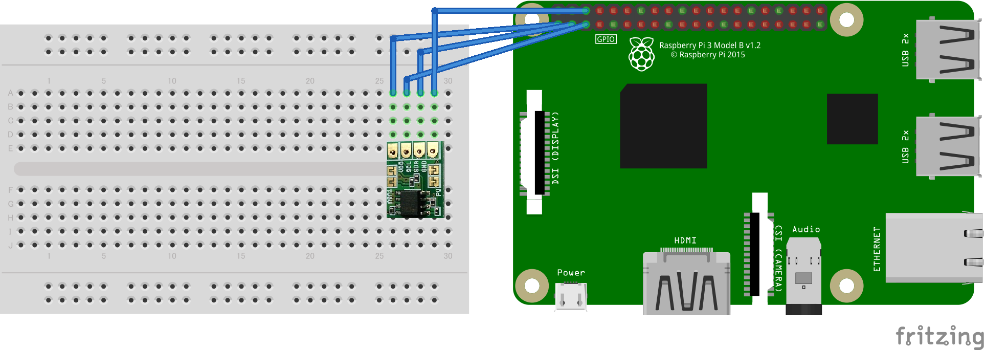
Although it is a Raspberry Pi in the above image, the actual wiring is done to the header pin on the PiConsole I / F.

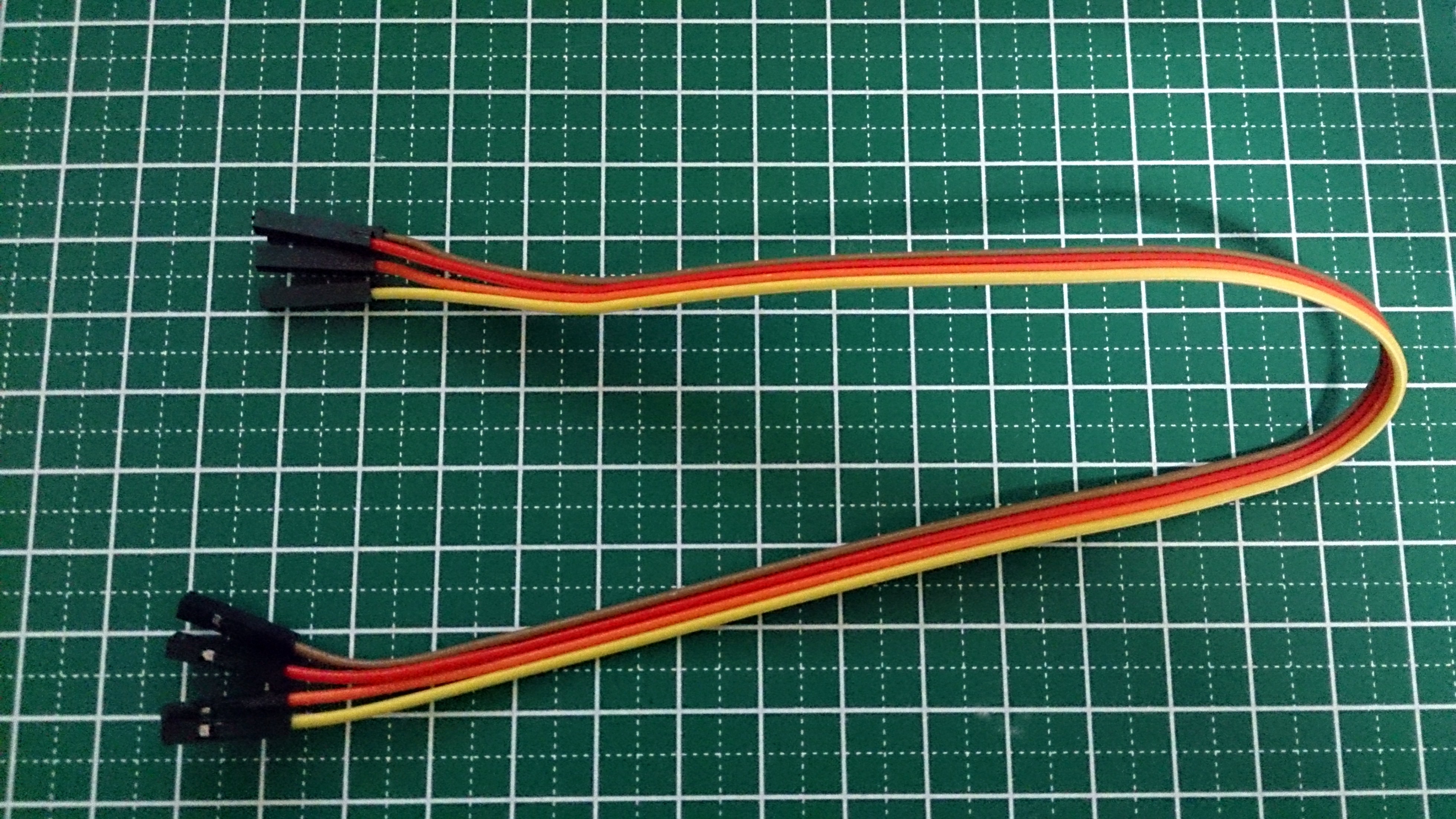
At this time, one is a male and the other is a female jumper pin, but if both have female jumper pins, you do not need a breadboard. This may be more convenient if you are experimenting with a temperature sensor.
First, check if it is recognized by the I2C bus.
On a terminal emulator
pi@raspberrypi:~/sandbox $ gpio i2cdetect
0	1	2	3	4	5	6	7	8	9	a	b	c	d	e	f
00:	--	--	--	--	--	--	--	--	--	--	--	--	--
10:	--	--	--	--	--	--	--	--	--	--	--	--	--	--	--	--
20:	--	--	--	--	--	--	--	--	--	--	--	--	--	--	--	--
30:	--	--	--	--	--	--	--	--	--	--	--	--	--	--	3e	--
40:	--	--	--	--	--	--	--	--	48	--	--	--	--	--	--	--
50:	--	--	--	--	--	--	--	--	--	--	--	--	--	--	--	--
60:	--	--	--	--	--	--	--	--	--	--	--	--	--	--	--	--
70:	--	--	--	--	--	--	--	--
'48' is the address of the temperature sensor module. Here, I confirmed it with the gpio command. It seems that it is recognized normally.
Further preparation is required. The temperature sensor module used here can measure with the original 16-bit resolution with a little setting. Refer to "[Enable I2C Repeated Start Condition on Raspberry Pi] URL for enabling I2C Repeated Start Condition on Raspberry Pi".
shell-session:/etc/modprobe.d/i2c.conf
options i2c_bcm2708 combined=1
After creating the above file, restart Raspberry Pi.
Then it is a script. First, check the operation of the temperature sensor module alone.
adt7410.py
#!/usr/bin/python
# -*- coding: utf-8 -*-

import wiringpi as wp
import time

I2C_ADDR_THERMO = 0x48

#2's complement representation conversion
# http://stackoverflow.com/questions/1604464/twos-complement-in-python
def twos_comp(val, bits):
    """compute the 2's compliment of int value val"""
    if (val & (1 << (bits - 1))) != 0: # if sign bit is set e.g., 8bit: 128-255
        val = val - (1 << bits)        # compute negative value
    return val                         # return positive value as is

class ADT7410:
    """
    ADT7410 thermometer control class
    """
    def __init__(self, i2c_addr = I2C_ADDR_THERMO):
        self.i2c = wp.I2C()
        self.fd = self.i2c.setup(i2c_addr)
        #Set the resolution to 16 bits
        self._write(0x003, 0x80)

    def _write(self, offset, data):
        self.i2c.writeReg8(self.fd, offset, data)

    def _read(self, offset):
        datum = self.i2c.readReg8(self.fd, offset)
        return datum

    def read_temp(self):
        msb = self._read(0x00)
        lsb = self._read(0x01)
        temp = (msb << 8 | lsb)  # MSB, LSB
        temp = twos_comp(temp, 16)
        return temp

if __name__ == '__main__':
    thermo = ADT7410(I2C_ADDR_THERMO)
    while True:
        temp = thermo.read_temp()
        print("Temperature:%6.2f" % (temp / 128.0))
        time.sleep(1)
The above script works by itself, so run it to check the operation.
On a terminal emulator
pi@raspberrypi:~/sandbox $ python3 adt7410.py
Temperature: 27.98
Temperature: 28.02
Temperature: 27.98
・ ・ ・
The temperature is displayed every second, so it is OK if a value close to room temperature is displayed. Also make sure that the temperature changes by touching the IC with your finger.
You can now use the temperature sensor module. The script of "If you press the button" is as follows.
b4.py
#!/usr/bin/env python3
# -*- coding:utf-8 -*-

import wiringpi as wp
PIN_SW1_WHITE = 19
PIN_SW2_BLACK = 16
PIN_LED1_RED = 20
PIN_LED2_YELLOW = 21
PIN_BUZZER = 25

from st7032i import St7032iLCD as LCD
I2C_ADDR_LCD = 0x3e

from adt7410 import ADT7410 as THERMO
I2C_ADDR_THERMO = 0x48

if __name__ == '__main__':
    wp.wiringPiSetupGpio()
    wp.pinMode(20,1)
    wp.pinMode(21,1)
    wp.pinMode(25,1)
    lcd = LCD(I2C_ADDR_LCD)
    thermo = THERMO(I2C_ADDR_THERMO)
    while True:
        sw1 = wp.digitalRead(PIN_SW1_WHITE)
        sw2 = wp.digitalRead(PIN_SW2_BLACK)
        if sw2 == 0:
            temp = thermo.read_temp() / 128.0
            lcd.clear()
            wp.delay(250)
            lcd.set_cursor(0, 0)
            lcd.print("{0:6.2f}".format(temp))
        wp.delay(250)
Execute and press SW2 (black) to display the temperature on the LCD screen.
On a terminal emulator
pi@raspberrypi:~/sandbox $ sudo python3 b4.py

Sample 5: Buzzer sounds when the value from the temperature sensor exceeds the threshold
(If you do not have an I2C-connected temperature sensor module, skip this item.)
b5.py
#!/usr/bin/env python3
# -*- coding:utf-8 -*-

import wiringpi as wp
PIN_SW1_WHITE = 19
PIN_SW2_BLACK = 16
PIN_LED1_RED = 20
PIN_LED2_YELLOW = 21
PIN_BUZZER = 25

from adt7410 import ADT7410 as THERMO
I2C_ADDR_THERMO = 0x48

if __name__ == '__main__':
    wp.wiringPiSetupGpio()
    wp.pinMode(20,1)
    wp.pinMode(21,1)
    wp.pinMode(25,1)
    thermo = THERMO(I2C_ADDR_THERMO)
    t1 = 32.0   #Threshold 1
    print("threshold t1:{0:6.2f}".format(t1))
    while True:
        sw1 = wp.digitalRead(PIN_SW1_WHITE)
        sw2 = wp.digitalRead(PIN_SW2_BLACK)
        temp = thermo.read_temp() / 128.0
        print("{0:6.2f}".format(temp))
        if temp > t1:
            print("over t1")
            wp.digitalWrite(PIN_BUZZER, 1)
        else:
            wp.digitalWrite(PIN_BUZZER, 0)
        wp.delay(500)
Let's do it. Since the threshold is set to 32 ° C, the buzzer sounds as soon as you touch it with your finger. The buzzer will stop when you release your finger and fall below the threshold.
On a terminal emulator
pi@raspberrypi:~/sandbox $ sudo python3 b5.py
threshold t1: 32.00
 30.59
 30.50
 30.49
 30.99
 31.42
 31.74
 31.97
 32.15
over t1
 32.28
over t1
 32.40
over t1
 32.52
over t1
 32.42
over t1
 32.17
over t1
 31.98
 31.70
Sample 6: Display the 3GPI connection status on the LCD
3 Displays the GPI connection status on the LCD. Regarding the APN setting of 3G PI 3G connection, it is a front miso, but "[Qiita: Cat Pi camera-connection test with DMM.com SIM] [Cat Pi camera-connection test URL with DMM.com SIM]" etc. Set it as a reference.
NetworkManager is used in 3GPI to manage connections, so prepare to use it from Python.
On a terminal emulator
pi@raspberrypi:~/sandbox $ sudo apt-get install python3-dbus
・ ・ ・
pi@raspberrypi:~/sandbox $ sudo pip3 install python-networkmanager
By the way, in the environment at hand based on 3gpi-20160208-2gb.img of the image for 3GPI, the dbus module could not be installed from pip3.
Check with the interpreter.
Check NetworkManager
Python 3.4.2 (default, Oct 19 2014, 13:31:11)
[GCC 4.9.1] on linux
Type "help", "copyright", "credits" or "license" for more information.
>>> import NetworkManager
>>> NetworkManager.NetworkManager.Version
'0.9.10.0'
>>> [(dev.Interface, dev.SpecificDevice().__class__.__name__)
...  for dev in NetworkManager.NetworkManager.GetDevices()]
[('lo', 'Generic'), ('eth0', 'Wired'), ('ttyUSB3', 'Modem')]
For the connection status, refer to the following part of info.py in the example of python-networkmanager.
print("%-30s %s" % ("Overall state:", c('state', NetworkManager.NetworkManager.State)))
The script was created based on sample 3.
b6.py
#!/usr/bin/env python3
# -*- coding:utf-8 -*-

import wiringpi as wp
PIN_SW1_WHITE = 19
PIN_SW2_BLACK = 16
PIN_LED1_RED = 20
PIN_LED2_YELLOW = 21
PIN_BUZZER = 25

from st7032i import St7032iLCD as LCD
I2C_ADDR_LCD = 0x3e

import NetworkManager
c = NetworkManager.const

if __name__ == '__main__':
    wp.wiringPiSetupGpio()
    wp.pinMode(20,1)
    wp.pinMode(21,1)
    wp.pinMode(25,1)
    lcd = LCD(I2C_ADDR_LCD)
    while True:
        sw1 = wp.digitalRead(PIN_SW1_WHITE)
        sw2 = wp.digitalRead(PIN_SW2_BLACK)
        if sw1 == 0:
            lcd.clear()
            wp.delay(250)
            lcd.set_cursor(0, 0)
            lcd.print("state:")
            state = "{0}".format(c('state', NetworkManager.NetworkManager.State))
            lcd.set_cursor(0, 1)
            lcd.print(state)
        wp.delay(500)
Every time you execute and press SW1 (white), the following is displayed.
state: disconnected
Turn on 3gpi with the 3gpictl utility and the display should change.
On a terminal emulator
pi@raspberrypi:~/sandbox $ 3gpictl --poweron
If your terminal is only serial, you can run the script in the background and run 3g pictl in the foreground.
On a terminal emulator
pi@raspberrypi:~/sandbox $ sudo python3 b6.py &
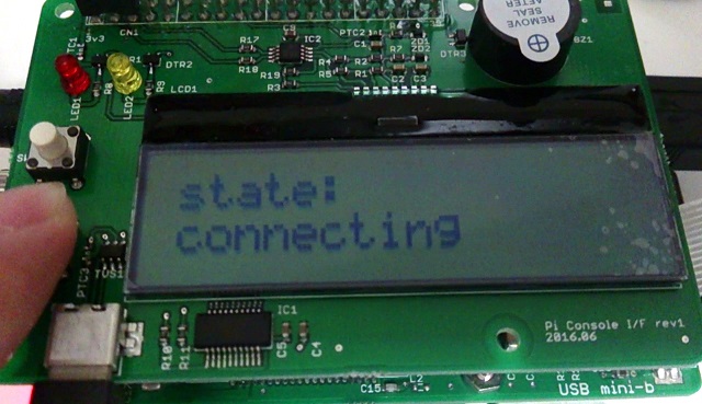
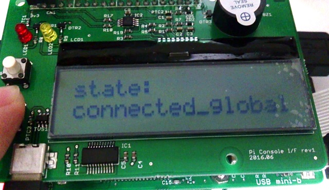
In the environment at hand, it changes from the disconnected state as follows.
・ Change from disconnected to connected
 ↓↓↓
↓↓↓
 ↓↓↓
↓↓↓
Advanced version
Create a sample that is slightly more complicated than the basic version.
Application 1: Implemented cup noodle timer (button, buzzer and LCD)
Implement a simple cup noodle timer.
specification
--Button 2 White press to switch between 3, 4 and 5 minutes --Press button 1 black to start --Display the remaining time on the LCD --Buzzer sounds when the time comes --Buzzer stops by pressing button 1/2
Implementation
It's a little long.
a1.py
#!/usr/bin/env python3
# -*- coding:utf-8 -*-

import wiringpi as wp
PIN_SW1_WHITE = 19
PIN_SW2_BLACK = 16
PIN_LED1_RED = 20
PIN_LED2_YELLOW = 21
PIN_BUZZER = 25

from st7032i import St7032iLCD as LCD
I2C_ADDR_LCD = 0x3e

from datetime import timedelta, datetime

class RamenTimer:
    """
    ramen-timer class
    """
    def __init__(self):
        self.lcd = LCD(I2C_ADDR_LCD)
        self.lcd.clear()
        self.timer = 3
        self.sw1_old = 1
        self.sw2_old = 1

    def beep(self, duration = 100):
        wp.digitalWrite(PIN_BUZZER, 1)
        wp.delay(duration)
        wp.digitalWrite(PIN_BUZZER, 0)

    def proc_inputs(self):
        sw1 =  wp.digitalRead(PIN_SW1_WHITE)
        if sw1 == 0 and self.sw1_old == 1:
            sw1_pushed = True
        else:
            sw1_pushed = False
        self.sw1_old = sw1
        sw2 =  wp.digitalRead(PIN_SW2_BLACK)
        if sw2 == 0 and self.sw2_old == 1:
            sw2_pushed = True
        else:
            sw2_pushed = False
        self.sw2_old = sw2
        return (sw1_pushed, sw2_pushed)

    def timer_select(self):
        while True:
            (sw1, sw2) = self.proc_inputs()
            if sw1:
                return
            if sw2:
                self.beep()
                self.timer = self.timer + 1
            if self.timer > 5:
                self.timer = 3
            self.lcd.clear()
            self.lcd.set_cursor(0, 0)
            self.lcd.print("{0}:00".format(self.timer))
            wp.delay(100)

    def timer_run(self):
        start = datetime.now()
        while True:
            (sw1, sw2) = self.proc_inputs()
            if sw1:
                return False
            delta = datetime.now() - start
            elapse = delta.seconds
            self.lcd.clear()
            self.lcd.set_cursor(0, 0)
            self.lcd.print("{0}:{1:02d}".format(int(elapse/60), elapse % 60))
            if elapse >= self.timer*60:
                return True
            wp.delay(250)

    def timer_buzz(self):
        count = 0
        while True:
            (sw1, sw2) = self.proc_inputs()
            if sw1 or sw2:
                wp.digitalWrite(PIN_BUZZER, 0)
                return
            if count in [0, 2, 4]:
                wp.digitalWrite(PIN_BUZZER, 1)
            else:
                wp.digitalWrite(PIN_BUZZER, 0)
            if count in [0, 2, 4, 6, 8]:
                wp.digitalWrite(PIN_LED1_RED, 1)
            else:
                wp.digitalWrite(PIN_LED1_RED, 0)
            count = (count + 1) % 10
            wp.delay(100)

if __name__ == '__main__':
    wp.wiringPiSetupGpio()
    wp.pinMode(20,1)
    wp.pinMode(21,1)
    wp.pinMode(25,1)
    wp.digitalWrite(PIN_BUZZER, 0)

    rt = RamenTimer()
    rt.timer_select()
    ret = rt.timer_run()
    if ret:
        rt.timer_buzz()
The button is triggered by "when pressed and released". The buzzer is implemented so that it sounds three times shorter. If you press the button during timer counting, it will end halfway. You can see the hassle of building a UI with GPIO.
Application 2: PiCamera
(If you do not have the PiCamera module, skip this item.)
This is a sample to take a picture when you press the button.
To use PiCamera, you need to enable the camera with raspi-config.
raspi-config>Enable Camera
After rebooting, you will be able to use the camera with the raspistill and raspivid commands.
The script was created by cutting and pasting the cup noodle timer.
a2.py
#!/usr/bin/env python3
# -*- coding:utf-8 -*-

import wiringpi as wp
PIN_SW1_WHITE = 19
PIN_SW2_BLACK = 16
PIN_LED1_RED = 20
PIN_LED2_YELLOW = 21
PIN_BUZZER = 25

from st7032i import St7032iLCD as LCD
I2C_ADDR_LCD = 0x3e

import os
from datetime import timedelta, datetime

class DamnCamera:
    """
    damn camera class
    """
    def __init__(self):
        self.lcd = LCD(I2C_ADDR_LCD)
        self.lcd.clear()
        self.sw1_old = 1
        self.sw2_old = 1

    def beep(self, duration = 100):
        wp.digitalWrite(PIN_BUZZER, 1)
        wp.delay(duration)
        wp.digitalWrite(PIN_BUZZER, 0)

    def proc_inputs(self):
        sw1 =  wp.digitalRead(PIN_SW1_WHITE)
        if sw1 == 0 and self.sw1_old == 1:
            sw1_pushed = True
        else:
            sw1_pushed = False
        self.sw1_old = sw1
        sw2 =  wp.digitalRead(PIN_SW2_BLACK)
        if sw2 == 0 and self.sw2_old == 1:
            sw2_pushed = True
        else:
            sw2_pushed = False
        self.sw2_old = sw2
        return (sw1_pushed, sw2_pushed)

    def run(self):
        while True:
            (sw1, sw2) = self.proc_inputs()
            if sw1:
                return False
            if sw2:
                self.lcd.clear()
                self.lcd.set_cursor(0, 0)
                self.lcd.print("<capturing...>")
                self.beep()
                fn = datetime.now().strftime('%m%d_%H%M%S.jpg')
                os.system("raspistill -o {0}".format(fn))
                self.lcd.clear()
                self.lcd.set_cursor(0, 0)
                self.lcd.print("{0}".format(fn))
                self.beep(200)
            wp.delay(250)

if __name__ == '__main__':
    wp.wiringPiSetupGpio()
    wp.pinMode(20,1)
    wp.pinMode(21,1)
    wp.pinMode(25,1)
    wp.digitalWrite(PIN_BUZZER, 0)

    cam = DamnCamera()
    cam.run()
When you press SW2 (black), a short buzzer sounds and you take a picture. When the saved image is completed, the buzzer sounds for a long time and the file name is displayed on the LCD screen. Press SW1 (white) to finish.
Application 3: Chattering countermeasures (debounce)
If you run the loop with a delay of 100 [msec] order on python like the sample of the basic part, it will be a countermeasure against chattering to some extent. I don't think it bothers me too much. On the other hand, if you use wiringPiISR as in sample 2, you will suffer from the chattering phenomenon.
Anyway, the following is a python script that captures the chattering phenomenon. Line breaks are added appropriately.
11111111111111111111111111111111111111111111111111111111111111111111111111111111
11111111111111111111111111111111111111111111111111111111111111111111111111111111
11111111111111111111111111111111111111111111111111111111111111111111111111111111
11111111111111111111111111111111111111111111111111111111111111111111111111111111
11111111111111111111111111111111111111111111111111111111111111111111111111111111
11111111111111111111111111111111111111111111111111111111111111111111111111111111
11111111111111111111111111111111110000000000000000000000000000000000000000000000
00000000000000000000000000000000000000000000000000000000000000000000000000000000
00000000000000000000000000000000000000000000000000000000000000000000000000000000
00000000000000000000000000000000000000000000000000000000000000000000000000000000
00000000000000000000000000000000000000000000000000000000000000000000000000000000
00000000000000000000000000000000000000000000000000000000000000000000000000000000
00000000000000000000000000000000000000000000000000000000000000000000000000000000
00000000000000000000000000000000000000000000000000000000000000000000000000000000
00000000000000000000000000000000000000000000000000000000000000000000000000000000
00000000000000000000000000000000110000000000000000000000000011111111111111111111
11111111111111111111111111111111111111111111111111111111111111111111111111111111
11111111111111111111111111111111111111111111111111111111111111111111111111111111
11111111111111111111111111111111111111111111111111111111111111111111111111111111
11111111111111111111111111111111111111111111111111111111111111111111111111111111
11111111111111111111111111111111111111111111111111111111111111111111111111111111
11111111111111111111111111111111111111111111111111111111111111111111111111111111
11111111111111111111111111111111
The script looks like this: I did this a few times and just pressed the button a few times to get the above phenomenon.
Chattering observation
    while True:
        sw1 = wp.digitalRead(PIN_SW1)

        wp.digitalWrite(PIN_LED_RED, ~sw1 & 1)

        print(sw1, end='')
One lap of the while loop is executed in less than 1 msec. The part of "... 0001100 ..." in the above result is considered to be the chattering phenomenon. If you write the script without thinking, the button is actually pressed only once, but it is pressed twice.
SW chattering in UI operations may not seem like a big deal if you don't care about operability, but chattering can often lead to chasing bugs in non-existent programs, so at least It should be supported by software. If the input chattering goes straight to the output, it causes more serious problems. For example, the life of geared motors will be extremely shortened.
Although it is a troublesome chattering countermeasure like this, the responsiveness of the input deteriorates depending on the countermeasure, whether it is hard or soft. For example, if you insert a timer or filter with a CR circuit, the input will be delayed accordingly. It means that it will be a problem with buttons and sensors that hit repeatedly at high speed.
Therefore, there is actually no "effective chattering countermeasure in any case". There is a trade-off. The important thing is not to take the story of "don't worry because there is hysteresis" or "chattering does not occur in the mercury switch". Chattering is a phenomenon on the order of msec at best, so even cheap oscilloscopes can be sufficiently observed, so it may be good to check with your own eyes.
In any case, the actual necessary measures cannot be determined only by the software, so it should be considered for the hardware and the entire system.
Finally
The PiConsole I / F has a simple structure of LED, button, buzzer, and LCD, but it is directly connected to Raspberry Pi and has a serial USB conversion, so it fits very compactly. It seems to be easy to carry around and demonstrate with a notebook PC.
・ Reposted 3 stories

Below is a photo of a similar I / O on a breadboard.
・ Spaghetti loading

It's quite annoying. I can't press the button because the jumper wire is in the way. With PiConsole I / F, it's a plug-and-play that can be used immediately by connecting it.
Also, the PiConsole I / F has header pins like 3GPI, so you can easily expand it by adding devices as in this article.
We hope you find this article useful for IoT device development.
Thank you for reading.
Link
[[anyPi] URL of anyPi [Mechatrax's site] [Mechatrax's URL] [3GPI] [URL of 3GPI] [Cat Pi Camera Article] URL of Cat Pi Camera with Raspberry Pi and 3GPI [Remote control OA tap article] Remote control OA tap URL [Pimetry system with 3GPI and OBDII] URL of Pimetry system with 3GPI and OBDII [SD image with 3GPI] [URL of SD image with 3GPI] [Qiita: Serial communication with Raspberry Pi3] [URL for serial communication with Raspberry Pi 3] [Qiita: AQM0802A / ST7032i LCD display using WiringPi-Python] URL of AQM0802A / ST7032i LCD display using WiringPi-Python [Enable I2C Repeated Start Condition on Raspberry Pi] URL for enabling I2C Repeated Start Condition on Raspberry Pi [Qiita: Cat Pi camera-DMM.com SIM connection test] [Cat Pi camera-DMM.com SIM connection test URL]
[Cat Pi camera-URL of connection test with SIM of DMM.com]: http://qiita.com/syasuda/items/5def33db425aaf05bf6d#dmmcom%E3%81%AEsim%E3%81%A7%E6%8E%A5 % E7% B6% 9A% E3% 83% 86% E3% 82% B9% E3% 83% 88
Recommended Posts