Let's draw the voltage of the digital multimeter 34461A of the measuring instrument Keysight with CircuitPython
CircuitPython Wi-Fi connection
The microcomputer board uses Adafruit Metro M4 Express AirLift (WiFi). This is the main feature.
- CPU 120MHz Cortex M4 ATSAMD51 (floating point, DSP, flash memory 512K bytes, RAM 192K bytes)
- External EEPROM 2MB
- Operating voltage 3.3V (DC jack 7-9V input, MicroUSB 5V input)
- Wireless ESP32-WROOM-32 SPI connection
- Analog (D-A converter) output A0 and A1 pins
- Interface bus I2C SPI

CircuitPython is 5.0.0 Beta 0 (https://github.com/adafruit/circuitpython/tags) ) Is used. Installation is omitted. When using Wi-Fi, the firmware of ESP32-WROOM-32 must be 1.3.0 or higher. Raise it to 1.4.0 or 1.5.0 according to Adafruit's instructions. See this article. https://www.denshi.club/pc/python/circuitpython/circuitpython-10-step3-1.html
Load esp32spi_simpletest.py in examples into the Mu editor and modify the two Wi-Fi router connections (router name and password) on line 40.
esp.connect_AP(b'MY_SSID_NAME', b'MY_SSID_PASSWORD')
Save it in main.py. Open the serial in the menu. The execution status is displayed at the bottom of the screen.

CircuitPython socket (BSD) is based on MicroPython
Docs »Quick Reference for ESP8266» MicroPython Tutorial for ESP8266 »5. Network-TCP Socket https://micropython-docs-ja.readthedocs.io/ja/latest/esp8266/tutorial/network_tcp.html If you look at the commentary article, it's different from a normal Python socket program.
import socket
Is the same, but
addr_info = socket.getaddrinfo("towel.blinkenlights.nl", 23)
Connect with the getaddrinfo () function. Then discard the unnecessary parts and
addr = addr_info[0][-1]
Connect with that addr.
s = socket.socket()
s.connect(addr)```

 I extracted the necessary parts from the sample.
import board import busio from digitalio import DigitalInOut import adafruit_esp32spi.adafruit_esp32spi_socket as sockets from adafruit_esp32spi import adafruit_esp32spi import adafruit_requests as requests import time
esp32_cs = DigitalInOut(board.ESP_CS) esp32_ready = DigitalInOut(board.ESP_BUSY) esp32_reset = DigitalInOut(board.ESP_RESET)
spi = busio.SPI(board.SCK, board.MOSI, board.MISO) esp = adafruit_esp32spi.ESP_SPIcontrol(spi, esp32_cs, esp32_ready, esp32_reset)
requests.set_socket(sockets, esp)
if esp.status == adafruit_esp32spi.WL_IDLE_STATUS: print("ESP32 found and in idle mode")
print("Connecting to AP...") while not esp.is_connected: try: esp.connect_AP(b'Buffalo-G-20EA', b'xxxxxx') except RuntimeError as e: print("could not connect to AP, retrying: ",e) continue print("Connected to", str(esp.ssid, 'utf-8'), "\tRSSI:", esp.rssi) print("My IP address is", esp.pretty_ip(esp.ip_address))
Next, we will describe how to connect the socket. On Windows and Raspberry Pi, .local can be used (mDNS and avahi), but CircuitPython does not support it, so write the IP address directly.
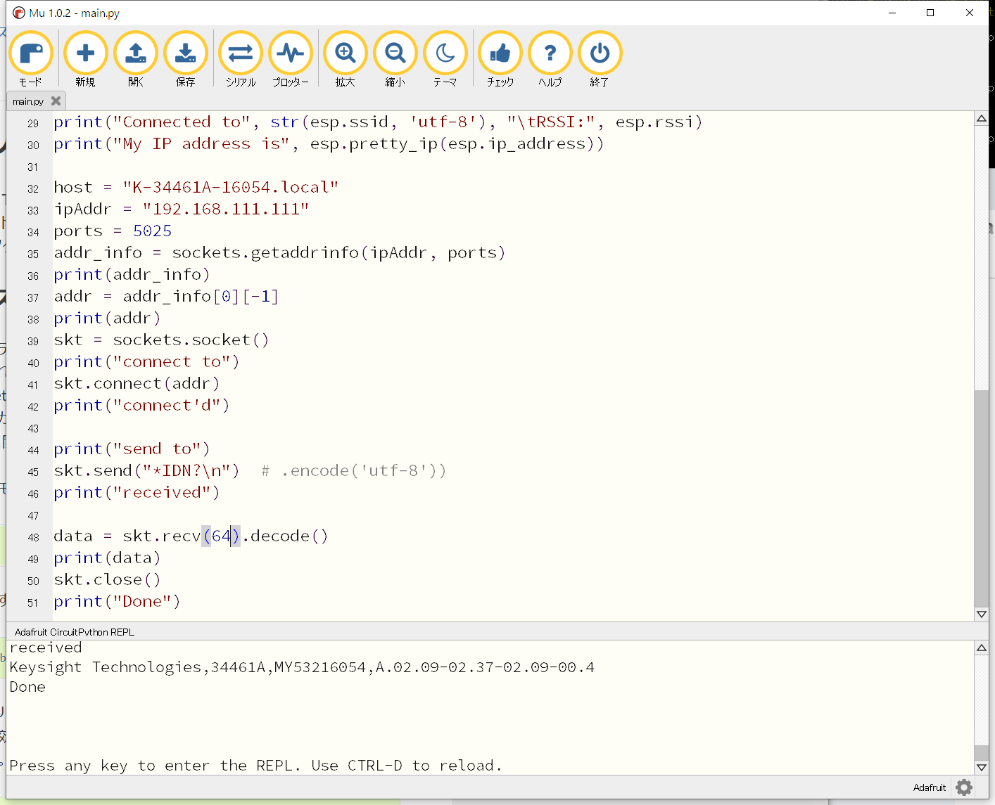
host = "K-34461A-16054.local" ipAddr = "192.168.111.111" ports = 5025 addr_info = sockets.getaddrinfo(ipAddr, ports) print(addr_info) addr = addr_info[0][-1] print(addr) skt = sockets.socket() print("connect to") skt.connect(addr) print("connect'd")
print("send to") skt.send("*IDN?\n") print("received")
data = skt.recv(64).decode() print(data) skt.close() print("Done")
Depending on the processing system, the recv () function that receives it will not terminate if the number of characters sent is less than the buffer. CircuitPython seems to have such a specification. This DMM returns about 70 characters for * IDN? Inquiring about the device name. Recv (256) did not finish receiving.
This is the execution result.

# Measure the voltage
import board import busio from digitalio import DigitalInOut import adafruit_esp32spi.adafruit_esp32spi_socket as sockets from adafruit_esp32spi import adafruit_esp32spi import adafruit_requests as requests import time
If you are using a board with pre-defined ESP32 Pins:
esp32_cs = DigitalInOut(board.ESP_CS) esp32_ready = DigitalInOut(board.ESP_BUSY) esp32_reset = DigitalInOut(board.ESP_RESET)
spi = busio.SPI(board.SCK, board.MOSI, board.MISO) esp = adafruit_esp32spi.ESP_SPIcontrol(spi, esp32_cs, esp32_ready, esp32_reset)
requests.set_socket(sockets, esp)
if esp.status == adafruit_esp32spi.WL_IDLE_STATUS: print("ESP32 found and in idle mode")
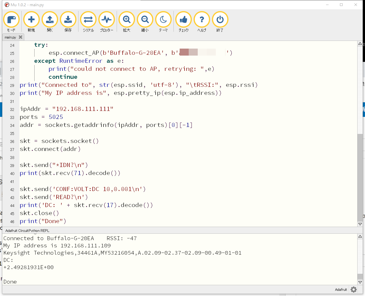
print("Connecting to AP...") while not esp.is_connected: try: esp.connect_AP(b'Buffalo-G-20EA', b'xxxxxxx') except RuntimeError as e: print("could not connect to AP, retrying: ",e) continue print("Connected to", str(esp.ssid, 'utf-8'), "\tRSSI:", esp.rssi) print("My IP address is", esp.pretty_ip(esp.ip_address))
ipAddr = "192.168.111.111" ports = 5025 addr = sockets.getaddrinfo(ipAddr, ports)[0][-1]
skt = sockets.socket() skt.connect(addr)
skt.send("*IDN?\n") print(skt.recv(71).decode())
skt.send('CONF:VOLT:DC 10,0.001\n') skt.send('READ?\n') print('DC: ' + skt.recv(17).decode()) skt.close() print("Done")
This is the execution result. The output of the experimental voltage source TL431 is connected to the measurement terminal of the DMM.

Recommended Posts