[PYTHON] Camera calibration
I found that the following translation is on the site of Tottori University.
[Camera Calibration and 3D Restoration](http://labs.eecs.tottori-u.ac.jp/sd/Member/oyamada/OpenCV/html/py_tutorials/py_calib3d/py_table_of_contents_calib3d/py_table_of_contents_calib3d.html#py-table- of-content-calib)
My crappy translation is no longer needed.
"OpenCV-Python Tutorials" in Japanese translation Camera Calibration I made a translation of. Original text in 3.1
Since it is a poor translation, there may be some mistakes in the translation of terms and the interpretation of sentences. For a solid understanding "Detailed OpenCV" It is highly recommended to read.
The original book has since been published in a version compatible with OpenCV3. Learning OpenCV 3 Computer Vision in C++ with the OpenCV Library I'd be happy if the Japanese translation of
Correction: I was giving the wrong translation for the circular grid. Retranslated as a grid of circles. (2016/5/7)
Camera Calibration {#tutorial_py_calibration}
Goal
In this section --Learn about camera distortion, camera internal and external parameters, and more. ――Learn how to find these parameters and correct the distortion of the image.
Basics
Today's cheap pinhole cameras have a lot of distortion. The two main distortions Radial distortion and circumferential distortion.
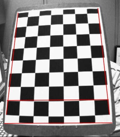
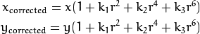
Due to the radial distortion, the straight line looks bent. The effect increases as you move away from the center of the image. As an example, one image is shown below. The two edges of the chess board are indicated by a red line. However, you will notice that the border is not a straight line and does not coincide with the red straight line. All expected straight lines bulge outward. For details, see [Distortion] Please ask (https://ja.wikipedia.org/wiki/%E6%AD%AA%E6%9B%B2%E5%8F%8E%E5%B7%AE).
This distortion is expressed as:
Similarly, the other distortion is circumferential distortion, which occurs in photographs taken with lenses that are not perfectly parallel to the image plane. Therefore, some areas in the image may appear closer than expected. The distortion is expressed as follows.
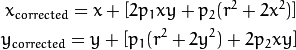
In short, you need to find the following five parameters known as the strain coefficients:

Translator's Note: The correction formula when there are two distortions is described in "Detailed OpenCV" p.399.
Besides this, you need to find some information. Internal and external parameters of the camera. Internal parameters are specific to each camera. It contains information such as focal length (\ f $ f_x, f_y \ f $) and optical center (\ f $ c_x, c_y \ f $). Also known as the camera matrix. The internal parameters depend only on the camera, so once calculated, they can be saved for future use. Internal parameters are represented by a 3x3 matrix.

External parameters correspond to rotation and movement vectors that make the coordinates of one 3D point correspond to another coordinate system.
For stereo applications, these distortions must first be corrected. All you have to do to find all these parameters is to provide a lot of sample images of one well-defined pattern (eg chess board). Find multiple feature points (square corners of the chessboard) on it. I know the coordinates in those real spaces, and I know the coordinates in the image. With these data, some mathematical problem is solved behind the scenes to get this distortion factor. That is a summary of the big picture. You will need at least 10 test patterns to get good results.
Code
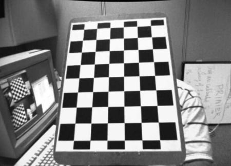
As mentioned above, at least 10 test patterns are required for camera calibration. OpenCV comes with multiple chessboard images. (See samples / cpp / left01.jpg --left14.jpg) Therefore, use it. For the sake of understanding, consider just one chess board. The important input data required for camera calibration is a set of 3D real-space points and corresponding 2D image points. Points on a 2D image can be easily found in the image. (These image points are where the two black squares touch each other on the chess board.)
Translator's Note: $(opencv)\sources\samples\data There is left01.jpg --left14.jpg in.
What about 3D points from real space? These images were taken from a fixed camera and the chess boards are placed in different positions and orientations. So you need to know (X, Y, Z). However, for simplicity, the chess board is in the XY plane (that is, always Z = 0) and you can assume that the camera is moving. With this consideration, you only need to find the X and Y values. As for the values of X and Y, you can simply pass multiple points in the manner of (0,0), (1,0), (2,0), .... In this case, the result we get is the value at the scale of the square size (30 mm) of the chess board. So you can pass values like (0,0), (30,0), (60,0), ... and you will get the result in mm. (In this example, we don't take these images, so we don't know the size of the square, so we're passing the size of the square as a unit.)
3D points are called ** object points **, and points on 2D images are called ** image points **.
Setup
To find a chessboard pattern ** cv2.findChessboardCorners () ** Use the function. You need to pass what kind of pattern you are looking for, for example, an 8x8 grid or a 5x5 grid. In this example, we use a 7x6 grid. (Usually, a chess board has an 8x8 square and 7x7 internal corners.) The function returns multiple corner points and a retval that returns True when a pattern is detected. These corners are in the order from left to right and top to bottom.
@sa This function may not be able to find the required pattern in all images. A good option in that case is to write the code, activate the camera and have each frame check the required pattern. Once you have the pattern, look for the corner and save it in the list. Leave a gap before reading the next frame. This allows the chess board to be adjusted in a different orientation. Continue this process until you have the required number of good patterns. Even in the example here, we are not sure how many sheets are good when we think away from the given 14. Therefore, all the images are read and treated as good.
@sa Instead of a chess board, you can use a circular grid. In that case, use ** cv2.findCirclesGrid () ** to find the pattern. It is said that a small number of sheets is sufficient when using a grid of circles.
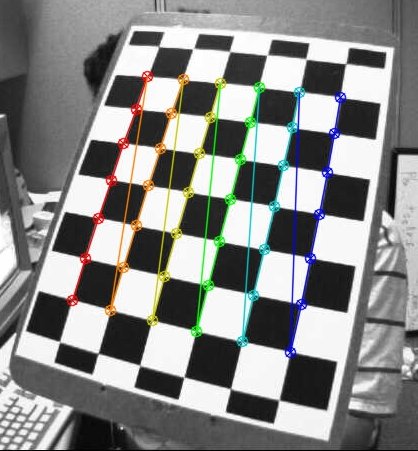
Once you find a corner, you can use ** cv2.cornerSubPix () ** to improve the accuracy of the corner. You can draw patterns using ** cv2.drawChessboardCorners () **. All of these steps are included in the code below.
python
import numpy as np
import cv2
import glob

# termination criteria
criteria = (cv2.TERM_CRITERIA_EPS + cv2.TERM_CRITERIA_MAX_ITER, 30, 0.001)

# prepare object points, like (0,0,0), (1,0,0), (2,0,0) ....,(6,5,0)
objp = np.zeros((6*7,3), np.float32)
objp[:,:2] = np.mgrid[0:7,0:6].T.reshape(-1,2)

# Arrays to store object points and image points from all the images.
objpoints = [] # 3d point in real world space
imgpoints = [] # 2d points in image plane.

images = glob.glob('*.jpg')

for fname in images:
    img = cv2.imread(fname)
    gray = cv2.cvtColor(img,cv2.COLOR_BGR2GRAY)

    # Find the chess board corners
    ret, corners = cv2.findChessboardCorners(gray, (7,6),None)

    # If found, add object points, image points (after refining them)
    if ret == True:
        objpoints.append(objp)

        cv2.cornerSubPix(gray,corners,(11,11),(-1,-1),criteria)
        imgpoints.append(corners)

        # Draw and display the corners
        cv2.drawChessboardCorners(img, (7,6), corners2,ret)
        cv2.imshow('img',img)
        cv2.waitKey(500)

cv2.destroyAllWindows()
The following is one image with the pattern written on it.
Calibration
Now that we have object points and image points, we are ready to calibrate. For proofreading, use ** cv2.calibrateCamera () **. This function returns the camera matrix, distortion factors, rotation and translation vectors, and more.
python
ret, mtx, dist, rvecs, tvecs = cv2.calibrateCamera(objpoints, imgpoints, gray.shape[::-1],None,None)
Undistortion
I found out that I was trying to do it. Now take a photo and correct the distortion. There are two methods for OpenCV. It is shown below. But before that, you can use ** cv2.getOptimalNewCameraMatrix () ** to improve the camera matrix based on the free scaling parameters. When scaling parameter alpha = 0, the function returns the distortion-corrected image in a way that minimizes the pixels you don't want. Therefore, you may want to remove some pixels in the corners of the image. When alpha = 1, all pixels are preserved and the part without the original data becomes a black image. The function also returns the ROI of the image and can be used to crop the result.
Now let's take a new image (we'll use left12.jpg here, the first image in this chapter).
python
img = cv2.imread('left12.jpg')
h,  w = img.shape[:2]
newcameramtx, roi=cv2.getOptimalNewCameraMatrix(mtx,dist,(w,h),1,(w,h))
Translator's Note: left12.jpg can be obtained from the following URL. Https://github.com/rajatsaxena/OpenCV
1. Use ** cv2.undistort () **
This is a quick procedure. Call the function and cut out from the result using the ROI obtained above.
python
# undistort
dst = cv2.undistort(img, mtx, dist, None, newcameramtx)

# crop the image
x,y,w,h = roi
dst = dst[y:y+h, x:x+w]
cv2.imwrite('calibresult.png',dst)
2. Use of remap
This is a roundabout procedure. First, find the mapping function from the distorted image to the distorted corrected image. Then use that remap function.
python
# undistort
mapx,mapy = cv2.initUndistortRectifyMap(mtx,dist,None,newcameramtx,(w,h),5)
dst = cv2.remap(img,mapx,mapy,cv2.INTER_LINEAR)

# crop the image
x,y,w,h = roi
dst = dst[y:y+h, x:x+w]
cv2.imwrite('calibresult.png',dst)
Both methods give the same result. See the results below.
In the resulting image you can see that all the edges are straight. Now you can save the camera matrix and distortion factor for later use using Numpy's write functions (np.savez, np.savetxt, etc.).
Re-projection Error
Reprojection error is a good way to evaluate how accurate the parameters found are. It is desirable that the value is as close to 0 as possible. Given the internal parameters, distortion, rotation, and parallel matrix, first use ** cv2.projectPoints () ** to convert the object points to image points. Then the norm of the difference between the conversion result and the corner detection algorithm (result) is calculated. To find the average error, calculate the arithmetic mean of the error for all of the calibration images.
python
mean_error = 0
for i in xrange(len(objpoints)):
    imgpoints2, _ = cv2.projectPoints(objpoints[i], rvecs[i], tvecs[i], mtx, dist)
    error = cv2.norm(imgpoints[i],imgpoints2, cv2.NORM_L2)/len(imgpoints2)
    tot_error += error

print "total error: ", mean_error/len(objpoints)
Additional Resources
Postscript by the translator "Camera calibration using a high-order polynomial model of an ultra-wide-angle, low-distortion lens" http://www.roboken.esys.tsukuba.ac.jp/~ohya/pdf/Robomech2014-KNS.pdf
Exercises
-# Try camera calibration with circular grid.
** Supplement by translator **
Supplement to "Camera Calibration" of OpenCV-Python Tutorials I made a separate article as.
List of OpenCV 2.4.0 sample sources (samples / cpp)
https://github.com/YusukeSuzuki/opencv_sample_list_jp/blob/master/samples_cpp.rst It is also useful to read a sample program related to stereo in C ++ from.
Tsai model
Tsai Camera Calibration http://homepages.inf.ed.ac.uk/rbf/CVonline/LOCAL_COPIES/DIAS1/ pyTsai - automated camera calibration in Python https://github.com/Csega/pyTsai/blob/master/doc/index.rst
Recommended Posts